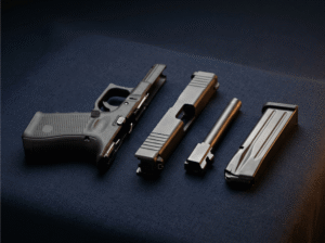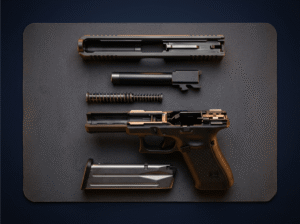

If you love a challenge or have never done your own gun build this is an awesome project. And depending on your location, where you buy and what you buy this can be a much cheaper option to owning an AR-15. This walkthrough will take you through the step by step instruction on how to build an AR-15 upper from parts. If you want an easier AR build you can buy finished uppers and lowers and do the install that way but we want to show you how to build one from the ground up.
How to Build an AR-15 Upper Receiver from Parts

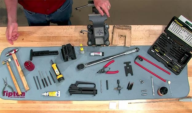
What tools you will need:
- Needle Nose Pliers
- A selection of hammers
- Drift Punches
- Roll pin starter punches
- center punch
- lithium grease
- light oil
- torque driver
- action block for the receiver
- torque wrench (30-80)
- Snap ring pliers
- Anti-Seize compound
- Gas tube alignment gauge
- front sight tool
- rear sight installation tool
- dummy rounds for function testing
- headspace gauges
- firing pin protrusion gauge
- magnet
- cleaning solvent
- Handguard tool
- screwdriver set
- caliper
Ejection Port Cover
1. Place Your E-clip

Always go slow and be patient. The tiny e-clip secures the rod that holds the injection port cover to the receiver. Its very tiny so use needle nose pliers and position the e-clip over the groove in the retaining pin and tap it into place with a hammer.

- 6-inch needle nose pliers with long tempered jaws for working in hard to reach areas, excellent for work in tight...
- Tapered nose with fine tips for bending wire, jewelry making, computers maintenance, electronics repair, small object...
- Great tool for general, hobby, or craft use, especially useful for jewelry craftsmen, artisans, electricians, and...
Last update on 2026-07-21 / Affiliate links / Images from Amazon Product Advertising API
2.Insert the Pin

Oil the injection port cover pin and place the smooth end of the pin through the right receiver boss and through the right side of the cover.
No products found.
3. Install the Spring

Lay the spring into position with the long end on the right side pointing up.
4. Check your Work

Hold the left side of the spring, rotate the right side of the spring down and insert the pin all the way through. Now you can test the cover for correct function.
No products found.
Forward Assist
Parts:
- Forward assist
- Return spring
- Roll pin
1. Grease your Parts

Oil the roll pin and grease the forward assist and spring
2. Secure the Receiver

Secure the receiver in a holding fixture and clamp the fixture in a vice.
3. Install the Forward Assist

Take the return spring and place it on the forward assist. Now insert this into the hole.
4. Punch your Roll Pin

Get the roll pin into position with a roll pin starter punch, then use a standard roll pin punch to drive it all the way in.
5. Test the Function

The forward assist assembly should now move freely in and out.
The Rear Sight
Parts:
- Rear sight installation tool
- Rear sight base index screw
- Rear sight elevation index wheel
- 1/16th inch allen wrench
- Rear site base
- Detent balls
- Springs
- Tensioner spring
- Elevation spring
- Rear sight flat spring
- Aperture
- Windage knob screw
- Windage knob
1. Screw in the Index Screw

Screw in the rear sight base index screw into the rear sight elevation index wheel with a 1/16th-inch hex wrench.
2. Combine the Wheel and Elevation Knob

Combine the index wheel with the elevation knob. It doesn’t matter which hole the index screw rests in.
3. Find your Detent Hole

Locate your detent hole. This is where a detent ball will be located. This ball places tension on the elevation knob which holds the elevation adjustment in position.
4. Install the Spring and Detent Ball

Place your spring in the detent hole then put a tiny bit of grease in the detent hole. Place the ball over the hole. The grease will hold the ball in position.
5. Insert the Elevation Knob

Now slide in the elevation knob assembly into the elevation knob slot. The detent ball should seed in any of the holes in the bottom of the elevation knob assembly.
6. Insert your Spring into the Tensioner Hole

Put some grease in the rear sight base tensioner hole. Now slide in the tensioner spring into the hole. Then put a tiny bit more grease on top.
7. Place another Detent Ball

Put another detent ball on top of this spring.
8. Install the Sight Base

Insert the sight base into the sight base hole and screw it into the elevation knob. Be sure to not dislodge the detent ball when you are doing this.
9. Insert Elevation Spring

Now put your elevation spring in the rear cavity of the rear sight base.
10. Compress the Spring

Use your rear sight installation tool to compress the spring while you put in the roll pin.
11. Use your Installation Tool for Accuracy

Take the body of sight installation tool and slide it into the receiver from behind so that the hole in the tool body is aligned with the cavity in the threaded portion of the sight base.
12. Compress the Elevation Spring

Now insert your fork spring depressor into the body of the tool and compress the elevation spring.
13. Insert the Tool Lock to Keep the Spring Compressed

Align the hole in the shaft with the hole in the center of the body of the sight installation tool. Now slide the tool lock into the tool body and through the shaft of the spring depressor. This will hold the tool in place and keep the elevation spring compressed properly.
14. Punch in your Roll Pin

Now use a roll pin starter punch to start the roll pin in the pin hole. Then finish it off with a standard roll pin punch.
15. Remove the Tools and Place the Flat Spring

Now remove the installation tools and lubricate the rear sight flat spring and place it in the recess on the top of the rear sight base.
16. Place your Aperture

Next place the aperture on the spring. The large hole should be placed facing upwards with the numbers readable. Now thread the windage knob screw through the aperture from the left side of the base.
17. Install the Windage Knob Screw

Turn the screw until it is fully seated and adjust the aperture until it is in the middle of the sight base.
18. Place a Spring and Detent Ball on the Windage Knob

Take your windage knob and put some grease in the detent hole on the rear of the knob. Put the spring in the hole and apply more grease. Now put the detent ball on the end of the spring.
19. Install the Windage Knob onto the Windage Screw

Take your knob and put it on the right side end of the windage knob screw. Again be sure to not drop the detent ball.
21. Punch in your Roll Pin

Align the holes in the windage knob and screw. Hold it together with a small punch and follow up from the other side with a roll pin. Now seat the pin with a roll pin punch.
22. Zero your Sights

Now use a 1/16 inch allen wrench to loosen the rear sight index screw and release the elevation knob from the indexing knob. Set your sights at zero then tighten the index screw to lock the pieces together.
Checking Headspace
Parts:
- Go Headspace Gauge
- No go Headspace Gauge
- Cleaning rod
- Bolt
1. Strip your Bolt

Start with a stripped bolt and your go and no-go gauges. Both the extractor and ejector need to be removed so that there are no false readings when checking the headspace.
2. Clean your Barrel

Clean the chamber thoroughly so that no brass or shavings get in the way.
3. Use the Go Gauge

Insert your go gauge and insert the bolt into the chamber. You should be able to turn the bolt and engage the locking lugs completely. This lets us know the chamber has at least the minimum amount of headspace.
4. Use the No-Go Gauge

Do the same thing with the no-go gauge. You should not be able to turn the locking lugs completely. If you are able to, you have too much headspace and shouldn’t fire the gun.
The Bolt
Parts:
- Bolt
- Springs
- Extractor
- Extractor Spring
- Roll Pins
- Ejector Spring
- Ejector
- 3 Gas Rings
1. Lubricate your Parts

Lubricate all the pins with light gun oil. Also add a bit of grease to each of the springs.
2. Install the Extractor Spring

Take your extractor spring and place it in the spring recess in the bolt.
3. Insert the Extractor

Now take your extractor and place it on the bolt and clamp it into place using a padded machinist device.
4. Punch in your Roll Pin

Take your roll pin and drive it all the way through the bolt.
5. Insert the Ejector Spring

Now insert the ejector spring into the recess on the bolt face.
6. Install the Ejector

Insert the ejector into the bolt and push it in with a flat faced punch.
7. Punch in your Roll Pin

Start your roll pin with a roll pin starter punch. Then use a roll pin punch to finish driving it in.
8. Install the Gas Rings onto the Bolt

Take your gas rings and place them on the groove of the bolt. Be sure that the open ends are not aligned. This will make sure the gas seal is not compromised.
The Bolt Carrier Key
Parts:
- Bolt Carrier
- Carrier Key
- Screws
- Staking Punch
- Torque Driver (Wheeler FAT Wrench)
- Ball Peen Hammer
1. Install the Screws

First you want to install the screws but they wont be enough to hold the key down.
2. Torque the Screws

Torque each screw to 35 inch pounds.
3. Stake the Screws

Place the staking punch at the edge of the screw and use the ball peen hammer to stake them.
4. Check your Work

Be sure to stake each screw twice.
The Bolt Carrier Assembly
Parts:
- Firing Pin
- Firing Pin Protrusion gauge
- Firing Pin Retainer
- Bolt
- Bolt Carrier
- Caliper
- Charging Handle
- Cam pin
1. Place the Firing Pin

Insert the firing pin into the bolt.
2. Zero your Gauge

Zero the firing pin gauge by loosening the set screw and pressing it against a flat surface. Now retighten the set screw.
3. Measure with Calipers

Measure the gauge with a caliper. This should give you a reading of .9 inches.
4. Use the Gauge

Again loosen the set screw on the firing pin gauge. Take you bolt with the inserted firing pin and press the gauge against the bolt face.
5. Measure with Calipers

Tighten the screw again and use the caliper to measure it. Subtract the two measurements and you want it to be in the acceptable range of 28-36 thousandths of firing pin protrusion.
6. Insert the Bolt into the Carrier

Insert the bolt without the firing pin into the bolt carrier.
7. Align the Cam Pin

Align the cam pin hole to the bolt with the cam pin slot in the bolt carrier. Install the cam pin with the cam pin head lengthwise along the carrier.
8. Rotate the Cam Pin Head

When the cam head is fully seated, rotate the head 90 degrees. The cam pin should be able to move freely in the cam pin slot.
9. Insert your Firing Pin

Now you can insert the firing pin.
10. Install the Firing Pin Retainer

Insert the firing pin retainer into the left side of the bolt carrier. Be sure that the retainer is fully seated in the recess.
11. Test the Firing Pin Security

Pull on the rear of the firing pin to make sure that it is secure.
12. Slide in your Charging Handle

Engage the tabs on the charging handle with the cuts on the carrier raceway by sliding the charging handle in slightly.
13. Put it Together

Now you can install the carrier by pushing it all the way forward into the frame.
No products found.
The Delta Ring
Parts:
- Barrel
- Barrel Sleeve
- Barrel Nut
- Delta Ring
- Well Spring
- Retaining Ring
- Snap ring Pliers
1. Place the Delta Ring

Next, slide the delta ring onto the barrel from the rear of the barrel nut.
2. Slide on the Well Spring

Slide the wellspring onto the barrel and into the delta ring.
3. Install the Retaining Ring

Now take your retaining ring and use a pair of snap ring pliers to open it and engage it onto the barrel nut to hold everything in place.
You can also check out this full video on How to Build an AR-15 Upper Receiver
Did you enjoy hearing about an How to Build an AR-15 Upper Receiver? Let us know in the comments section below what your thoughts are on this. Do you have any other gun topics you’d like to share? Share it with us and we’ll check it out. We are highly interested anything firearms and want to share and inform you of the latest and best information. That’s why we created this site, we want people to be more in touch with quality firearms information so that you can arm and defend yourself effectively in any situation.We would love to hear what you think and stay connected with us.